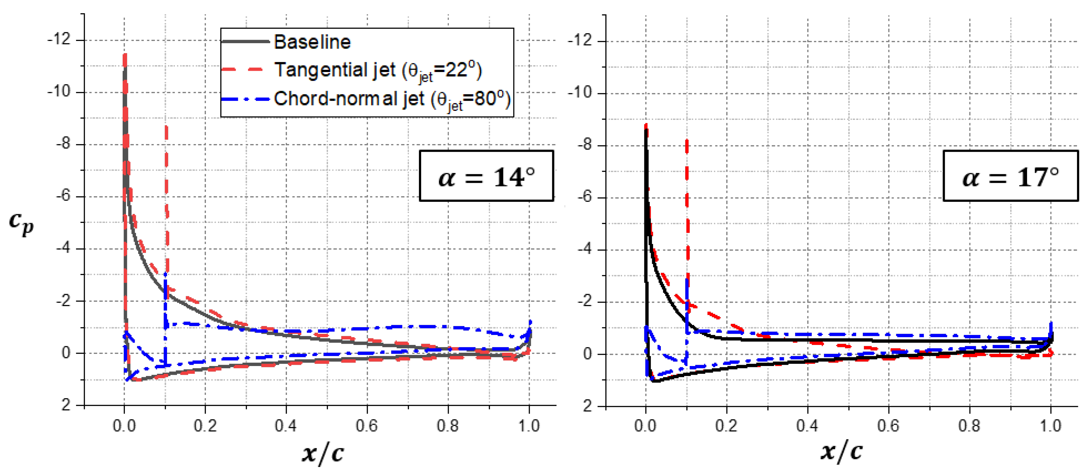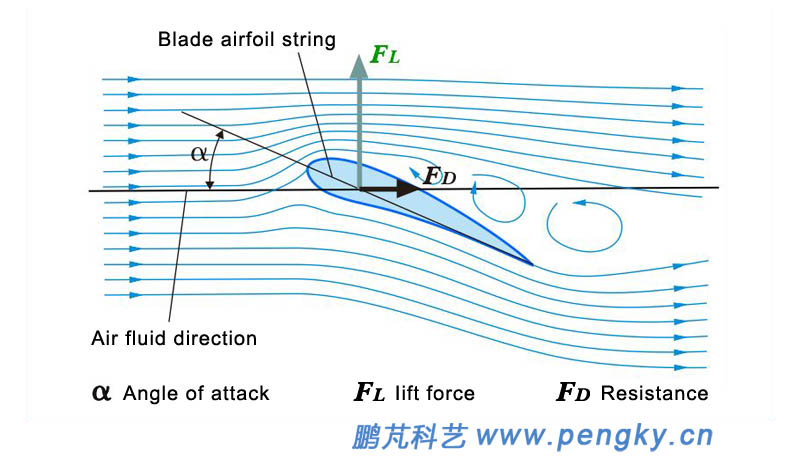

Usually, the airfoil can be classified based on geometry as either asymmetrical or symmetrical airfoil. However, the lift produced is different depending upon the shape of the airfoil. As the rotor blade passes through the air, the downward force on the airfoil helps to develop a significant lift, enabling a successful flight. This is the exact mechanism that allows aircraft such as planes or helicopters to stay up in the air. The resulting pressure difference helps in creating a lift. The pressure in the upper part of the airfoil decreases as the flow stretches over the curved upper surface as compared to the flat lower section where the speed and pressure of the flow remain the same.

When the airfoil is subjected to flow, its streamlined shape allows the flow to split between the upper and lower surfaces of the airfoil. The airfoil is streamlined in shape and can be of many designs for different speed requirements. Airfoil and LiftĪirfoil, in aerodynamic terms, is the cross-sectional shape of an object, such as wings, rotors, or sails, that is used to generate a lift. This article aims to explore cambered and symmetrical airfoil in detail. However, for the analysis, it is necessary to understand airfoil and identify how its geometry plays an important role in assessing aerodynamic performance. Through characterization of the airfoil, CFD can facilitate analysis of its efficiency when exposed to various speed and force parameters. With the help of computational fluid dynamics (CFD), this prediction can be made in a much faster and easier manner. Especially in aeronautics engineering, the study of various aerodynamic parameters over the airfoil provides information on pressure distribution, lift, or drag force. When fluid flows around certain structural geometries such as airplanes and automotive or marine components, the knowledge of how the flow parameter interacts is of utmost importance to engineers and system designers. System designers can use CFD sol\vers to simulate and visualize symmetrical airfoil performance at different flow conditions. The symmetrical airfoil cannot produce any lift at a zero angle of attack. This yields to flow stabilization, inhibition of stall, and in turn,Ĭounterclockwise dynamic polar along with augmented total lift.In symmetrical airfoil, the upper section is identical to that of the lower section. To the conclusion that the flow and particularly the stalled wake of an airfoilįacing a three-dimensional gust are strongly coupled in the spanwise direction. Local inflow, total lift as well as certain liftĮvents are captured by one POD eigenmode, respectively. A proper orthogonal decomposition (POD)Īnalysis of the flow field contributes to understand aerodynamic consequences

$1/8$ period between evolution of local angle of attack and lift giving aĬounterclockwise dynamic polar. The aerodynamic response of the airfoil shows a delay of about Stall cycle is divided into five stages of which one reveals lift overshoot of Streamwise and spanwise periodic variation are investigated by comparing totalĪnd local lift generation with flow formation above the airfoil. Light dynamic stall is thus analyzed in a wind tunnel. Aerodynamic behavior of a DU 91-W2-250 wind profile undergoing Particularly theįormation of dynamic stall under three-dimensional inflow conditions raises Temporary overshoot of lift and detrimental fatigue loads.
#Airfoil stall pdf#
Download a PDF of the paper titled Dynamic stall of an airfoil under tailored three-dimensional inflow conditions, by Dominik Traphan and 5 other authors Download PDF Abstract: Rotor blades of wind turbines in the atmospheric boundary layer regularlyĮxperience the aerodynamic phenomenon of dynamic stall consisting of a


 0 kommentar(er)
